![]()
![]()
![]()
![]()
| Mesh Generation > Mesh Editing > Surface normal and tangent direction |
|
|
|
|
||
Surface normal and tangent directions
VisualFEA uses surface normal directions for various purposes including model rendering, force assignment, local coordinates of a shell element and so on. The normal direction at a specific point on a surface mesh is determined by the element containing the point. It is related to the node numbering within the element. The tangent directions are especially important for a shell element with its local coordinates based on the surface normal and tangent directions. They are defined by the surface normal and the global coordinate axes. You can identify the surface normal and tangent directions, and reverse the directions if necessary.
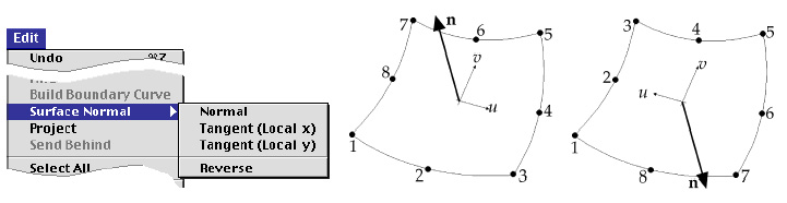
<Node numbering and normal direction on an element>
> Displaying the surface normal direction
To display the surface normal, select surface meshes whose normal directions
are to be displayed. And choose the "Normal" item of ![]() submenu.
Then, a surface normal vector is drawn at the center of each element constituting
the surface meshes.
submenu.
Then, a surface normal vector is drawn at the center of each element constituting
the surface meshes.
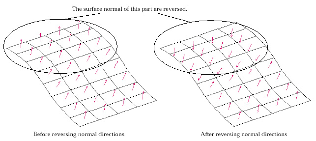
<Example of reversing surface normal direction>
> Displaying surface tangent directions
There are two tangent directions which makes 3 orthogonal axes along with the
surface normal. The tangent directions are also the local coordinates axes used
in shell elements. To display the directions tangent to the surface, select
surface meshes whose tangent directions are to be displayed. And choose the
"Tangent (Local x)" or "Tangent (Local y)" item of ![]() submenu.
The local x direction of a shell element is displayed by selecting "Tangent
(Local x)" item, and the local y direction by "Tangent (Local y)".
submenu.
The local x direction of a shell element is displayed by selecting "Tangent
(Local x)" item, and the local y direction by "Tangent (Local y)".
> Reversing surface normal directions
The surface normal directions can be reversed by selecting surface meshes and
choosing "Reverse" item of ![]() submenu.
Reversion of a normal vector on an element results in reversing the node numbering
within the element.
submenu.
Reversion of a normal vector on an element results in reversing the node numbering
within the element.
|
|
|
|