![]()
![]()
![]()
![]()
| Mesh Generation |
|
|
|
|
||
Mesh Generation
The finite element method requires dividing the analysis region into many subregions. These small regions are the elements, which are connected with adjacent elements at their nodes. Mesh generation is a procedure of generating the geometric data of the elements and their nodes, and involves computing the coordinates of nodes, defining their connectivity and thus constructing the elements. Here, mesh designates aggregates of elements, nodes and lines representing their connectivity.
Capability and convenience of modeling the analysis domain are dominated by the mesh generation procedure. The geometric characteristicsVolume mesh generation by sweeping operations of generated elements a ffect the overall performance and accuracy of the finite element analysis. Therefore, mesh generation is one of the most important procedures in finite element modeling.
General procedure of mesh generation
Various methods of mesh generation are provided in VisualFEA. However, the general procedure of mesh generation is almost the same whichever method is used, as can be summarized by the following few steps:
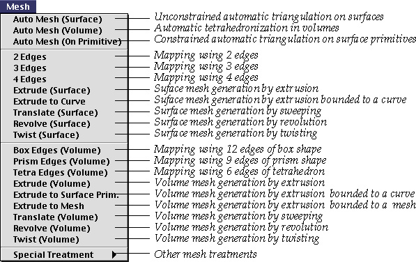
| 1) Activate one of the mesh generation commands. | |
| Choose a mesh generation command from |
|
| 2) Select curves or surface meshes, which are used as a seed of mesh generation. | |
| For example, a surface mesh may be generated by revolving a selected curve about a specified axis. In this case, the selected curve is used as a seed of the mesh generation. | |
| 3) Set the dialog items. | |
| The dialog has various selectable items to set the shape of element, number of nodes, input methods and so on. Some input text items are provided for defining characteristics of the mesh generation. | |
| 4) Input axis or path if necessary. | |
| The axis of rotation or path of sweeping is needed for some mesh generation schemes, and may be determined by selecting an existing curve or creating a new one. | |
| 5) Press appropriate buttons in the dialog. | |
| Buttons vary depending on the input stage. When everything is ready for mesh generation, the button approving mesh generation is enabled. Mesh is generated by clicking the button. | |
| 6) Repeat step 2) - 5) for next mesh generation. | |
| It is not necessary to issue the same command again to use the same method for further mesh generation. | |
| 7) In order to terminate the mesh generation command, activate other commands, or click the close box of the dialog. | |
| The mesh generation command is effective as long as the dialog remains on the screen. The command is terminated either by closing the dialog or by activating other command. |
The specific procedures are diff e rent for each of the mesh generation schemes as detailed in the following sections.
|
|
|
|