![]()
![]()
![]()
![]()
| Mesh Generation > Mesh Editing > Transforming meshes |
|
|
|
|
||
Transforming meshes
Meshes can be moved, resized or rotated as a whole. In other words, the geometry of selected meshes and their subordinate objects can be transformed. This capability of VisualFEA is useful more frequently in displaying analysis results which is described in the "Visualizing Scalar Data by Contours" section of Chapter 7. Mesh transformation applies only to surface and volume meshes, but not to frame meshes.
> Moving meshes
 |
You may move the selected meshes either by dragging the bounding box or by entering distances of movement in X, Y and Z directions as explained in the following: |
| 1) Click surface selection tool |
|
| 2) Select the meshes to move. | |
| Selected meshes are included in the list of the meshes to move. | |
| 3) Click object movement tool |
|
| A bounding box surrounding the selected meshes is drawn on the screen. The bounding box may be a rectangle or a right hexahedron, as shown in the following example, depending on the spatial dimension formed by the meshes to move. If all the nodes within the meshes have an identical coordinate in any one of X, Y or Z, the bounding box is reduced to a rectangle. | |
 |
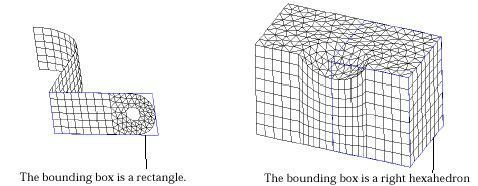 <
Bounding boxes surrounding planes and 3-D volumes > <
Bounding boxes surrounding planes and 3-D volumes > |
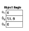
| At this stage, editable text boxes displaying the distances of movement in X, Y and Z directions appear at the bottom of the tool palette as shown at left. | |
| 4) Place the screen cursor on one edge of the bounding box, and press the mouse button. | |
| The direction of movement is set as parallel to the selected edge. | |
| 5) Move the mouse with the button pressed. | |
| The bounding box moves by sliding on the selected edge. The distance of movement is determined by the cursor movement, and is displayed on the text boxes at the bottom of the tool palette. | |
| 6) Release the mouse button. | |
| The bounding box settles at the final position where the mouse button is released. The selected meshes also are moved to the new position. The meshes can be moved to the desired position by repeating step 4), 5) and 6) with diff e rent edges. Or, the desired movement may be achieved at once by directly entering the offset distances in the editable text boxes of the tool palette. |
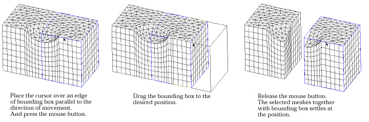
< Moving meshes by dragging the bounding box >
> Rotating meshes
 |
You may rotate selected meshes either by turning the bounding box using the mouse or by entering the angles of rotation about X, Y and Z axis as explained in the following: |
| 1) Click surface selection tool |
|
| 2) Select the meshes to rotate. | |
| Selected meshes are included in the list of the meshes to rotate. | |
| 3) Click object rotation tool |
|
| A bounding box surrounding the selected meshes is drawn on the scre e n . Editable text boxes displaying the angles of rotation about X, Y and Z axes appear at the bottom of the tool palette as shown left. | |
| 4) Place the screen cursor on one edge of the bounding box, and press the mouse button. | |
| The axis of rotation is set to be parallel to the selected edge, and to pass through the centroid of the bounding box. | |
| 5) Move the mouse with the button pressed. | |
 |
The bounding box rotates about the coordinate axis parallel to the selected edge. The angle of the rotation is determined by the edge moving along the cursor movement. The angle of rotation is continuously updated on the text boxes at the bottom of the tool palette, while the bounding box is being rotated. |
| 6) Release the mouse button. | |
| The bounding box settles with the final orientation where the mouse button is released. The selected meshes are also rotated to the new orientation in accordance with the bounding box. The meshes can be rotated to the desired orientation by repeating step 4), 5) and 6) with different edges. Or, the desired rotation may be achieved at once by directly entering the angles of rotation about each coordinate axis in the editable text boxes of the tool palette. |
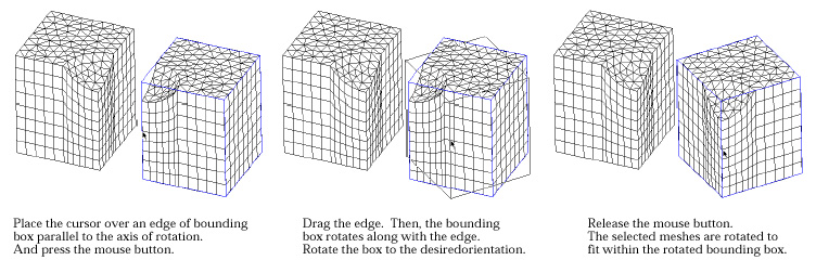
< Rotating meshes by dragging an edge of the bounding box >
> Resizing meshes
 |
You may resize the selected meshes either by rubber-banding the bounding box or by entering the relative scale in X, Y and Z axis as explained in the following: |
| 1) Click surface selection tool |
|
| 2) Select the meshes to resize. | |
| Selected meshes are included in the list of the meshes to resize. | |
| 3) Click object resizing tool |
|
 |
A bounding box surrounding the selected meshes is drawn on the scre e n . Editable text boxes displaying the relative scales of the meshes in X, Y and Z axes appear at the bottom of the tool palette as shown left. The relative scales are set to 1 at the beginning. |
| 4) Place the screen cursor on one edge of the bounding box, and press the mouse button. | |
| The direction of the resizing is set as parallel to the selected edge. | |
| 5) Move the mouse with the button pressed. | |
| The bounding box expands or shrinks in the direction parallel to the selected edge. The relative scale is determined by the movement of the cursor on the edge. If the cursor moves toward the center of the edge, the relative scale is reduced and the selected meshes shrink. If the cursor moves toward the ends of the edge, the meshes expand. The relative scale is continuously updated on the text boxes at the bottom of the tool palette, while the bounding box is being resized. | |
| 6) Release the mouse button. | |
| The bounding box settles with the final scale designated by the cursor position where the mouse button is released. The selected meshes are also resized to the new scale in accordance with the bounding box. |
The meshes can be resized to the desired scale by repeating step 4), 5) and 6) with d i ff e rent edges. Or, the desired resizing may be achieved at once by directly entering the relative scale in each coordinate axis in the editable text boxes of the tool palette.
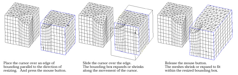
< Resizing meshes by rubber-banding an edge of the bounding box >
Instead of resizing only in one edge direction, you may resize the meshes with
equal relative scale in X, Y Z direction. This can be done by pressing ![]() key
(Windows :
key
(Windows : ![]() key)
while resizing the meshes following the above procedures.
key)
while resizing the meshes following the above procedures.
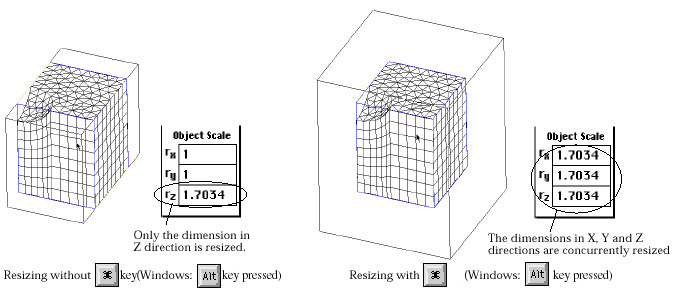
< Resizing meshes with and without ![]() key
(Windows :
key
(Windows : ![]() key)
pressed >
key)
pressed >
|
|
|
|