![]()
![]()
![]()
![]()
| Mesh Generation > Mesh Editing > Modifying nodal coordinates |
|
|
|
|
||
Meshes consist of a number of nodes and elements. You may modify the coordinates of nodes, one by one, and accordingly the shape of the elements connected to the nodes. This can be done either by using mouse or by using keyboard. But, nodes on the mesh boundaries cannot be modified individually.
> Dragging nodes using mouse
You may drag individual nodal points interactively by using the mouse as explained in the following:
| 1) Click node selection tool |
|
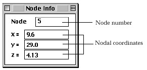
| 2) Double click the node to drag. | |
| The node is marked with a small blue rectangle, and "node Info" dialog box appears. The dialog has the basic information on the marked node. If "node Info" dialog is already on the screen, you don'n have to double click to invoke the dialog. Instead, click the node only once. Then, the contents of the dialog are renewed. | |
 |
|
| 3) Position the screen cursor over the node and press the mouse button. | |
| 4) Move the mouse with the button pressed. | |
| The screen cursor moves, and the nodal point moves along with the cursor movement. While the node is moving, the updated nodal coordinates are continuously echoed as texts in the "node Info" dialog. At the same time, the boundary lines of the elements connected to the node are also modified. Accordingly the modified shape of the elements are drawn on the screen. | |
| 5) Release the mouse button. | |
| The node is settled the the point where the mouse button is released. | |
| 6) Repeat step 3), 4), 5) until the node is placed on the desired position. |
While "Node Info" dialog box is on, clicking another node will switch the node to drag. The contents of the dialog box are also renewed. So, you may drag nodes one after another by repeating step 3) through 6). In order to quit dragging nodes, close "node Info" dialog by clicking the close box of the dialog.
You must make sure that the corresponding grid plane is on and contains the point to which the node is to be dragged. The reason is that VisualFEA constrains the movement of cursor by the grid plane.
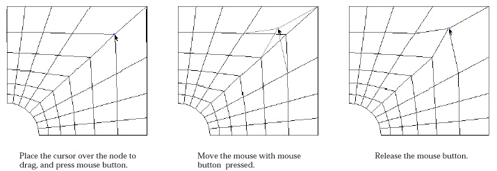
< Process of dragging a node >
> Modifying nodal coordinates by keyboard input
Nodes can be moved to the desired position by directly entering the coordinates of the nodes using keyboard.
| 1) Click node selection tool |
|
| 2) Double click the node to drag. | |
| The node is marked with a small blue rectangle, and "Node Info" dialog box appears. | |
| 3) Edit the coordinates of the node to modify using the dialog. | |
| The coordinates of the node are displayed as editable texts on the dialog, and can be edited one by one. | |
| 4) Press |
|
| The edited texts are entered as the new coordinates of the node, and the nodal point moves to the new position. The shape of the elements connected to the node is accordingly modified. |
While "Node Info" dialog is on the screen, the contents of the dialog are renewed with the information of another node by simply clicking the node. You can modify the coordinates of the node, the information of which is currently displayed on the dialog.
> Changing node number
The node numbers can also be modified using "node Info" dialog described
above. Edit the text representing the node number and press ![]() key
(Windows :
key
(Windows : ![]() key).
Then, the node number is changed into the newly entered number. If the modified
number is less than original one, all the node numbers between them will be
increased by one. If the modified number is g reater than original one, all
the node numbers between the original and the modified nodes will be decreased
by one.
key).
Then, the node number is changed into the newly entered number. If the modified
number is less than original one, all the node numbers between them will be
increased by one. If the modified number is g reater than original one, all
the node numbers between the original and the modified nodes will be decreased
by one.
 |
A node shared by 2 or more adjacent mesh regions may be unintentionally separated into more than one nodes, owing to limited precision of computation. This happens rarely, but its consequence may be critical. Such unintentionally separated nodes may be merged into one by the following steps. |
| 1) Click node selection tool |
|
| 2) Select nodes in the range of suspected nodal separation. Assume roughly the range which may contain separated nodes, and select the nodes within the range. Or select all the nodes in the model, if it is difficult to assume the region. | |
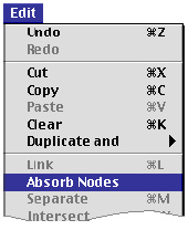
| 3) Choose "Absorb Node" item from |
|
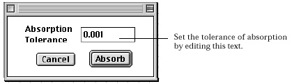
| A dialog for setting absorption tolerance pops up on the screen. Edit the editable text of absorption tolerance, which is the limiting distance for node absorption. | |
 |
|
| 4) Click |
|
| The nodes within tolerance distance from each other are merged into one. New nodal coordinates are determined by averaging the coordinates of the merged nodes. |
|
|
|
|