![]()
![]()
![]()
![]()
| Diagrams for Frame Analysis > Diagrams for Truss and Rigid Frame > Visualizing analysis data of 2-D and 3-D trusses |
|
|
|
|
||
Visualizing analysis data of 2-D and 3-D trusses
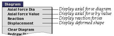
If the analysis type is set to either 2-D or 3-D truss, ![]() menu has the items as shown below. The menu has only axial force items as for
member forces. In addition, it has support reaction and displacement
items. The following analysis results are available for 2-D and 3-D trusses.
menu has the items as shown below. The menu has only axial force items as for
member forces. In addition, it has support reaction and displacement
items. The following analysis results are available for 2-D and 3-D trusses.
|
Axial force |
|
|
Support reaction |
|
|
Displacement |
It is assumed that all truss members are pin-connected at the joints. Thus, truss members are subject to only axial force. The data from truss analysis are relatively simple, and can be visualized efficiently either by diagrams or by text strings.
> Displaying axial force diagram
It is assumed in VisualFEA that all truss members are straight, and forces
are acting only at their joints, but not in the middle of the members. Thus,
the axial force in a truss member is always uniform throughout its entire length.
To display the axial force by diagram, choose "Axial Force Dia" item
from ![]() menu. An example of axial force diagram is shown below.
menu. An example of axial force diagram is shown below.
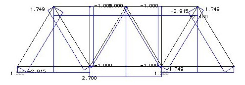
<Axial force diagram >
> Displaying axial force value
As the axial force in a truss member is uniform, it is simpler to express the
value of the force magnitude by the text than to display its diagram. To display
the axial force by text, choose "Axial Force Value" item from ![]() menu.
If the axial force is compressive, the value bears negative sign and is represented
in red letters. Otherwise, the value is positive and represented in blue letters.
menu.
If the axial force is compressive, the value bears negative sign and is represented
in red letters. Otherwise, the value is positive and represented in blue letters.
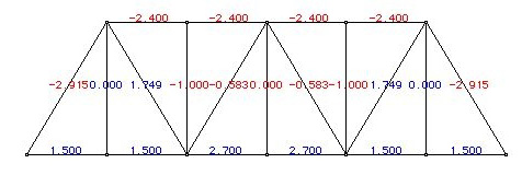
< Axial force magnitude represented in text string >
> Displaying reactions at supported nodes
To display the support reactions, choose "Reaction" item from ![]() menu
. The reactions are represented by a force symbol and the text of its magnitude.
The reactions are shown only for constrained DOFs with non-zero value at supported
nodes.
menu
. The reactions are represented by a force symbol and the text of its magnitude.
The reactions are shown only for constrained DOFs with non-zero value at supported
nodes.
< Axial force magnitude represented in text string >
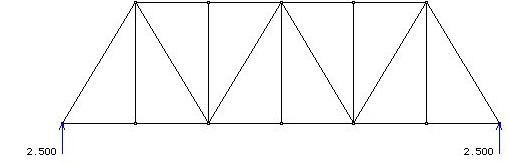
> Displaying displacements
To display the displacements of the truss, choose "Displacement"
item from ![]() menu.
It is assumed that a truss member has only axial deformation. Accordingly, each
member is re p resented by a straight line before and after deformation.
menu.
It is assumed that a truss member has only axial deformation. Accordingly, each
member is re p resented by a straight line before and after deformation.
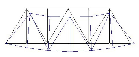
< Axial force magnitude represented in text string >
|
|
|
|