![]()
![]()
![]()
![]()
| Mesh Generation > Surface Mesh Generation > Automatic triangulation |
|
|
|
|
||
Automatic triangulation is the most convenient and powerful method of generating surface meshes. There are two types of automatic triangulation for surface mesh generation, i.e., unconstrained and constrained. Unconstrained automatic triangulation is to generate a mesh using the selected curves only. In this case, there are no other constraints for mesh generation than the curves inside and at the boundary of the region. This type of automatic triangulation is chiefly used for generating a plane mesh. Constrained automatic triangulation is to generate a mesh on a predefined surface primitive. This type of automatic triangulation is useful for generating a mesh on a trimmed surface.
> Generating mesh on a plane by automatic triangulation
 |
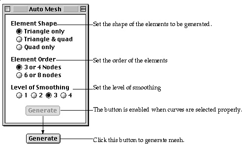
The easiest way of generating mesh on a plane is "Unconstrained" automatic triangulation. An arbitrarily shaped surface mesh is generated simply by designating the curves of the mesh boundary and issuing a mesh generation command. A curved surface as well as a plane may be meshed by this method. However, it is advisable to limit the usage of this method to a plane mesh, and for a curved surface mesh to apply "Constrained" automatic triangulation as explained in the later section. You can easily fill an arbitrarily shaped surface region with triangular or quadrilateral elements using automatic triangulation as described below. |
In the above procedure, the order of step 2), 3), 4) and 5) can be interchanged. You may repeat the above Quadratic procedure of generating mesh by automatic triangulation without issuing the command again, while "Auto Tri" dialog remains on the screen. This mesh generation command is terminated by closing the dialog box or issuing any other command.
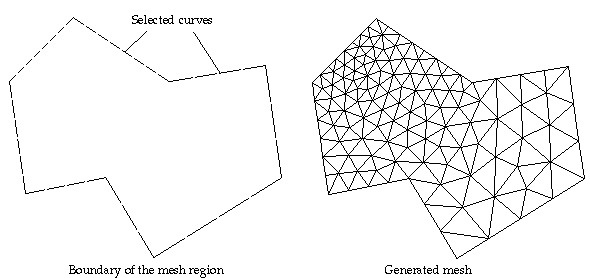
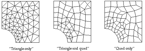
< Example of automatic triangulation >
> Setting a compatible region for automatic triangulation
For successful automatic triangulation, curves should be selected so that they may form a region compatible for mesh generation as described below.
| The outer boundary of the region should be enclosed by serially connected curves. | |
| All the selected curves should be in one united region. | |
| The region boundary may be either convex or concave. | |
| The region may contain holes or control curves inside the boundary. | |
| Curves inside the region may cross or contact with each other, but they must have a common node at each crossing or contacting point. |
If you issue the automatic triangulation command with improper curve selection, you may receive one of the responses shown from VisualFEA depending on the state of the curve selection.
| The command is ignored with a warning message. It is the error message expected in most cases. | |
| The mesh is generated improperly. Undo the mesh generation, or delete the mesh, and retry with newly selected curves. | |
| You may get unpredictable results, and sometimes system crash. VisualFEA avoids this situation as much as possible. Such a situation rarely happens. But there may be still special cases which have not been excluded. The following examples illustrate mesh regions compatible and incompatible for automatic triangulation. |
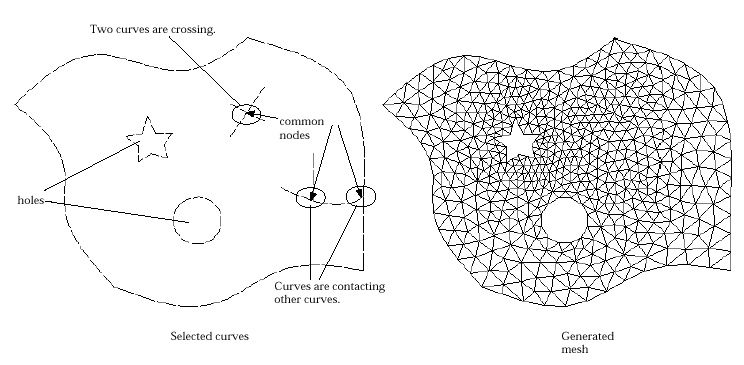
< An example of compatible region for automatic triangulation >
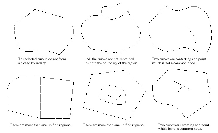
< Examples of incompatible region for automatic triangulation >
> Handling the incompatibility due to mismatching curve ends
Although you selected curves compatible for automatic triangulation, you may not get a successful mesh generation. It is the case in which there exists visually unidentifiable incompatibility in the formation of boundary curves. The major source of such incompatibility is the numerical errors in various operations related to curves including curve-curve intersection. You may get a notice dialog box as shown below.
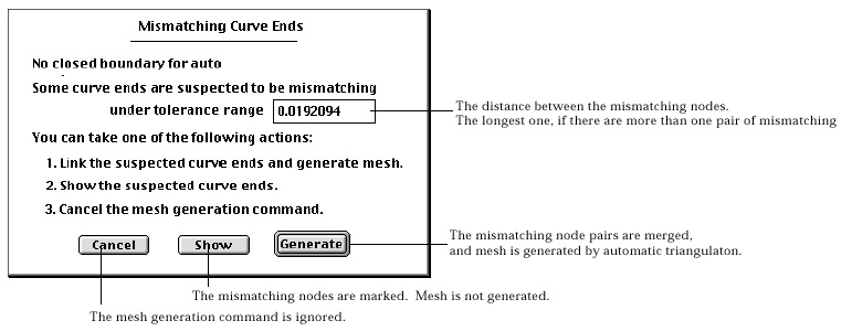
The dialog box informs that the boundary curves are not closed probably because some curve ends are mismatching. You may choose one of the 3 buttons provided by this dialog box.
boundary curves are close. You may set the tolerance range of the gap to be closed.
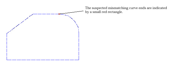
< A example of showing mismatching curve ends >
> Generating mesh on a surface primitive by automatic triangulation
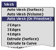 |
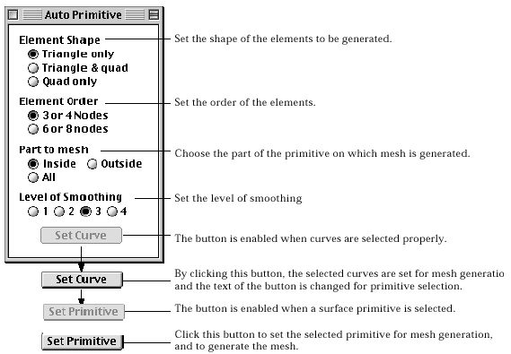
You may create surface primitives such as spheres, cylinders, toru s , Bezier surface and so on (refer to "Creating surface primitives". A mesh can be generated using selected curves and a surface primitive. The mesh is bounded and controlled by the selected curves, and at the same time, is confined on the surface primitive. |
You may repeat the above procedure of generating mesh on a surface primitive, without issuing the command again, while "Auto Primitive" dialog remains on the screen. This mesh generation command is terminated by closing the dialog box or issuing any other command.
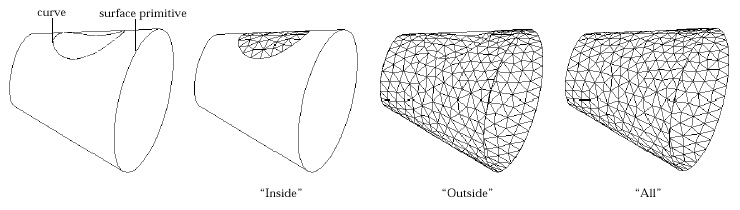
< Comparison of meshes generated using different options of part to mesh >
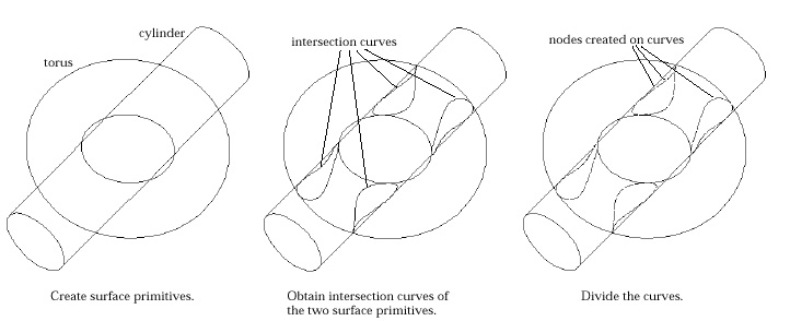
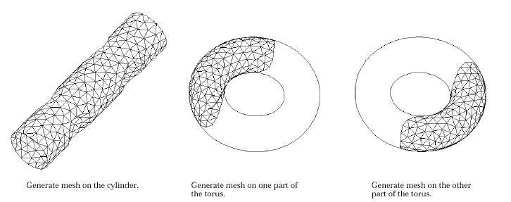
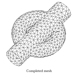
< Example of mesh generation using surface primitives and their intersection curves >
|
|
|
|