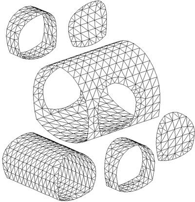
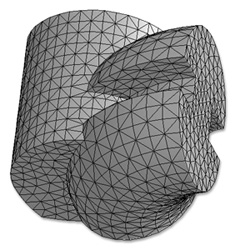
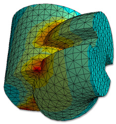
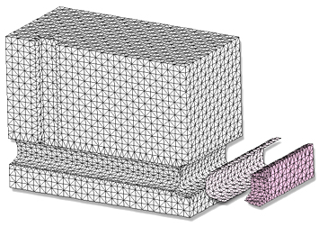
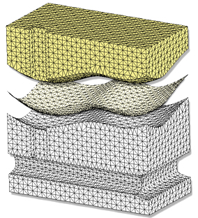
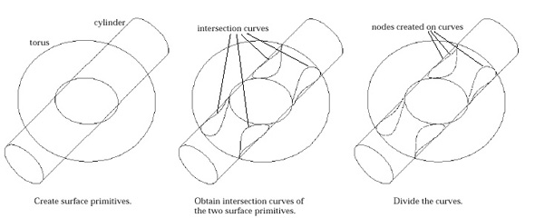
Intersection
is a powerful mesh manipulator which facilitates modelling of
complex surface geometry. The intersection curves are defined
along the points spatially shared by two or more independently
created surface meshes. They split each of the surface meshes
into parts. All the mesh parts edged with a common intersection
curve are inter-connected at the nodes on the curve.
The mesh elements crossing over the intersection curves are removed.
And then, the gaps are filled by elements newly generated in align
with the intersection curves.

  |
|||||||||
| Mesh
A, B |
|||||||||
|
|||||||||
 |
|||||||||
 |
|||||||||
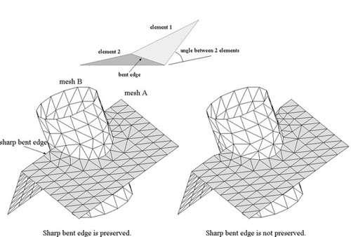
| Example
of "Aware Sharp Bent" edge |
|||||||||
 |
|||||||||
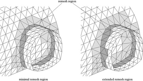
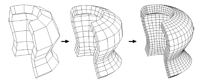
| Adjustment
of remesh region |
|||||||||
|
|||||||||
|
|||||||||
|
|||||||||
|
|||||||||||||||
|
|||||||||||||||
|
Mesh Refinement
|
|||
 |
|||
|
Example of
subdividing a volume mesh
|
|||
 |
|||
|
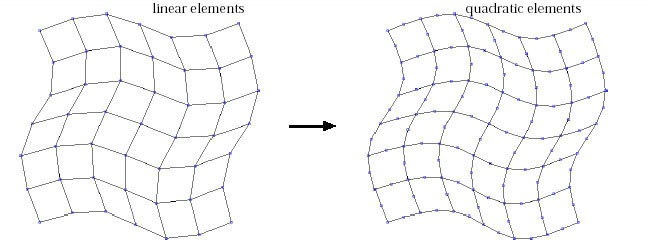
Conversion
of linear elements to quadratic
|
|||
 |
|||
|
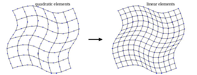
Conversion of quadratic
elements into linear
|
|||
|
Meshes can
be refined by subdivision or by convertion of linear elements
into quadratic order. Reversely, quadratic elements may also be
split into linear elements. These operations of mesh refinement
are applied to the whole model at once, and cannot be undone.
|
|||
|
Automatic mesh generation - 2D
|
|||
 |
|||
|
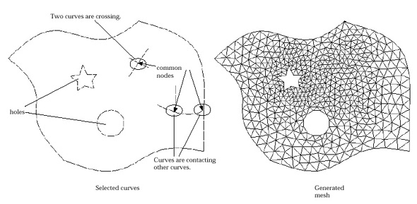
An example
of compatible region for automatic triangulation
|
|||
|
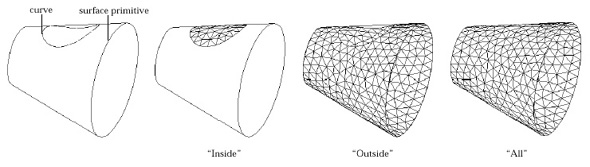
Generating mesh on a surface primitive
|
|||
 |
|||
|
Comparison of meshes generated
using different options of part to mesh
|
|||
 |
|||
 |
|||
 |
|||
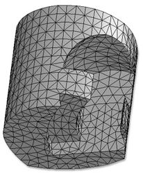
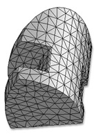
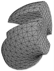
|
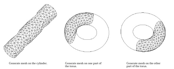
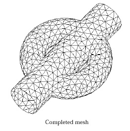
Example of mesh generation
using surface primitives and their intersection curves
|
|||
|
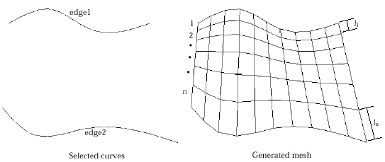
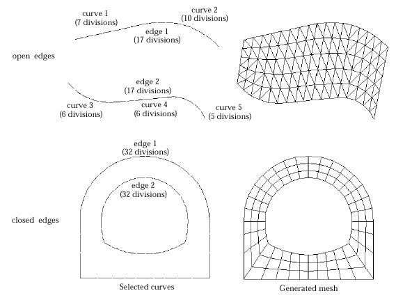
Surface mesh generation by mapping
|
|||
 |
|||
|
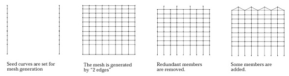
Example of surface mesh
generation between 2 edges
|
|||
|
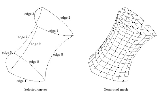
Generating mesh 2 edges compatible
|
|||
 |
|||
|
Examples of 2 edge formation
compatible for mesh generation
|
|||
|
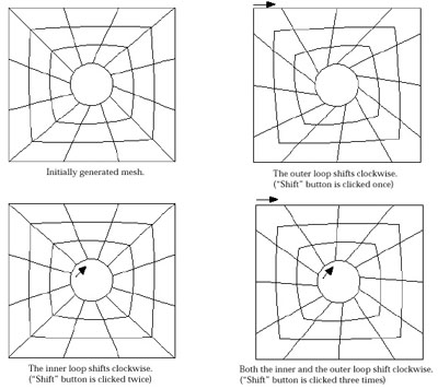
Shifting alignment of node pairing on 2 edges
|
|||
 |
|||
|
Example of alignment shifting
in looped 2 edges
|
|||
|
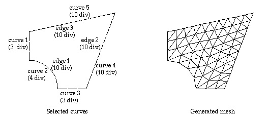
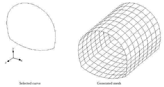
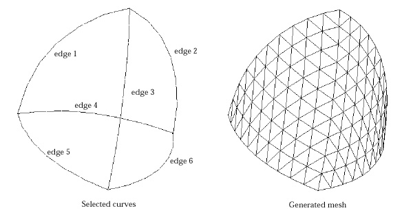
Generating mesh using 3 edges
|
|||
 |
|||
|
Example of surface mesh
generation enclosed by 3 edges
|
|||
|
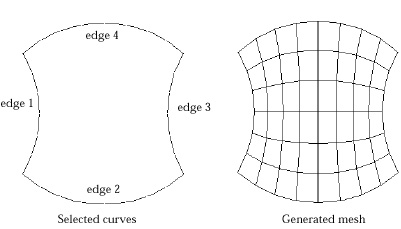
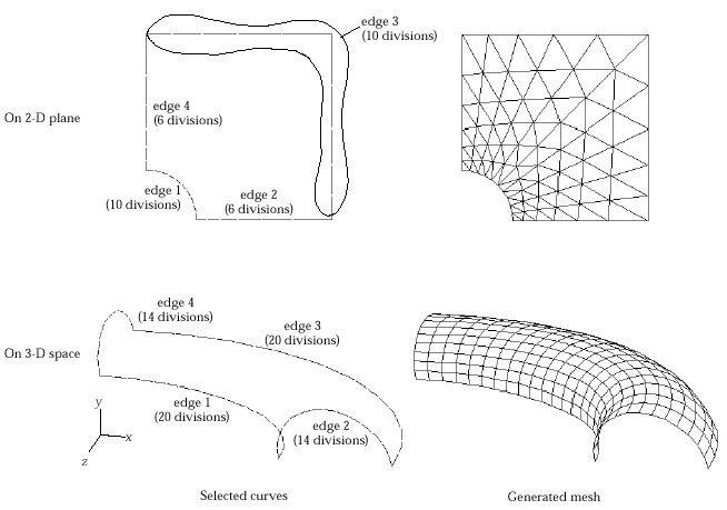
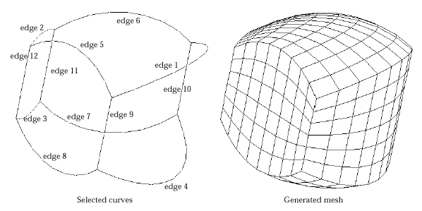
Generating mesh using 4 edges
|
|||
 |
|||
|
Example of surface mesh
generation enclosed by 4 edges
|
|||
|
Generating mesh 4 edges compatible
|
|||
 |
|||
|
Examples of 4 edge formation
compatible for mesh generation
|
|||
|
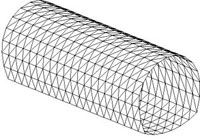
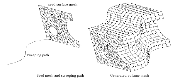
Surface mesh generation by sweeping operations
|
|||
 |
|||
|
A 3-D surface mesh generated
by extrusion in an out-of-plane direction
|
|||
|
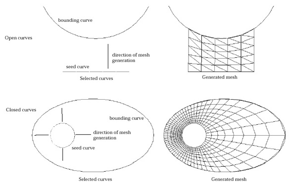
Generating mesh by extrusion up to bounding
curves
|
|||
 |
|||
|
Mesh generated by extrusion
up to bounding curves
|
|||
|
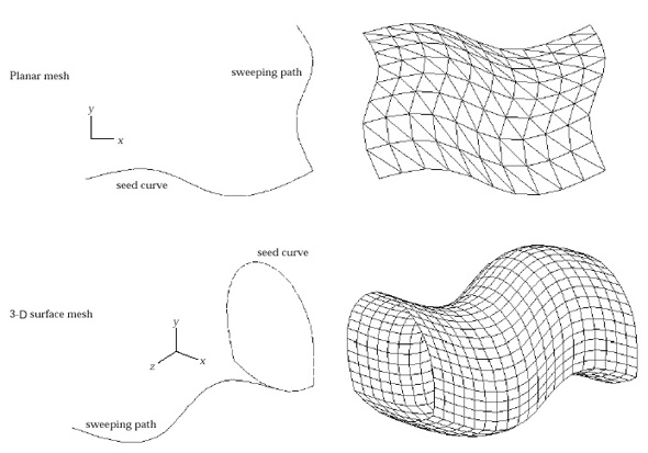
Generating mesh by translation
|
|||
 |
|||
|
Example of mesh generation
by translation on plane and in 3-D space
|
|||
|
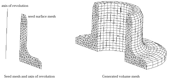
Generating mesh by revolution
|
|||
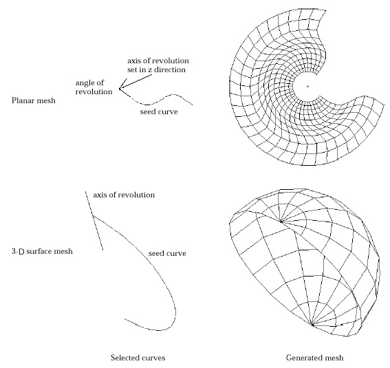 |
|||
|
Example of mesh generation
by revolution in a plane and in 3-D space
|
|||
|
Generating mesh by twisting
|
|||
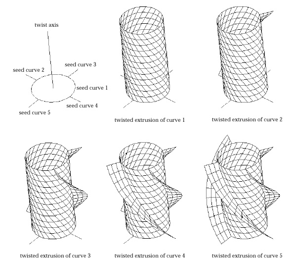 |
|||
|
Example of modeling 3-D
surfaces by twisting
|
|||
|
Projecting surface meshes
|
|||
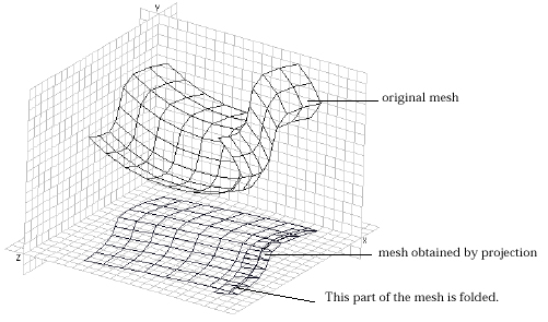 |
|||
|
Example of a faulty projection
|
|||
|
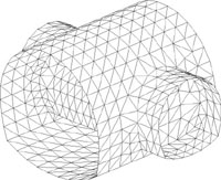
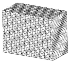
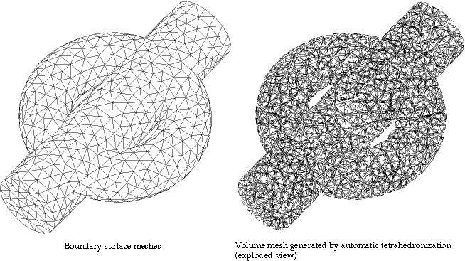
Volume mesh generation by automatic tetrahedronization
|
Generating mesh by automatic tetrahedronization
|
||
 |
|||
|
Example of volume mesh
generation by automatic tetrahedronization
|
|||
|
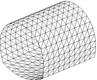
Volume mesh generation by mapping
|
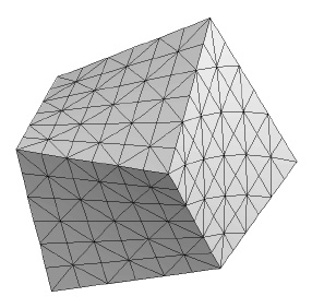
Generating mesh using box edges
|
||
 |
|||
|
Example of mesh generation
in a box edge region
|
|||
|
Generating mesh box edges compatible
|
|||
 |
|||
|
Formation of Union Jack on surfaces of a box edge volume mesh |
|||
|
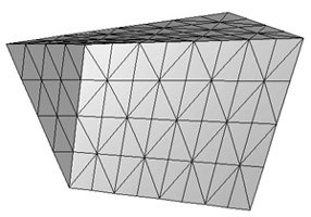
Generating mesh using prism edges
|
|||
 |
|||
|
Example of mesh generation in a prism edge region |
|||
|
Generating mesh prism edges compatible
|
|||
 |
|||
|
Formation of Union Jack on surfaces of a prism edge mesh |
|||
|
Generating mesh using tetrahedron edges
|
|||
 |
|||
|
Example of mesh generation in a tetra edge region |
|||
|
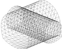
Volume mesh generation by sweeping operations
|
|||
 |
|||
|
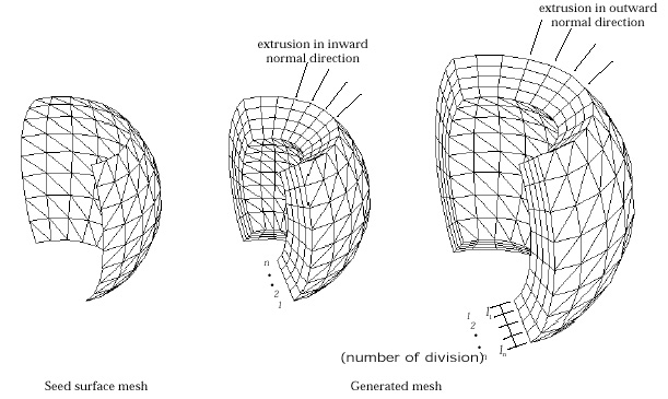
A volume mesh generated
by extrusion in normal direction
|
|||
|
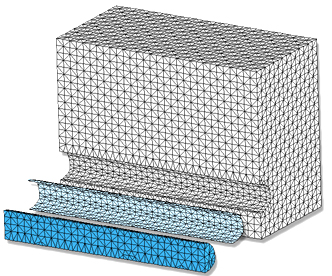
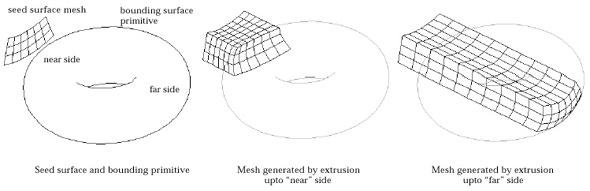
Generating mesh by extrusion up to bounding
surface primitives
|
|||
 |
|||
|
Example of mesh generation by extrusion to a surface primitive |
|||
|
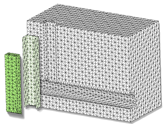
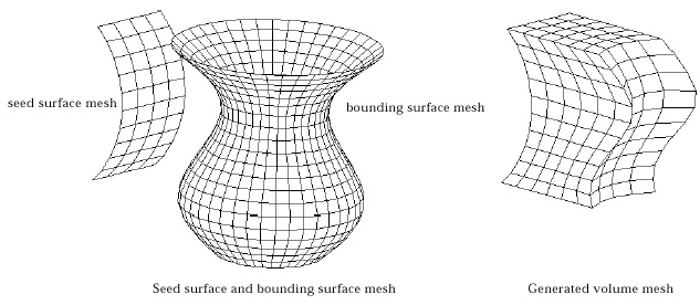
Generating mesh by extrusion up to surface meshes
|
|||
 |
|||
|
Example of mesh generation by extrusion to a surface mesh |
|||
|
Generating volume mesh by translation
|
|||
 |
|||
|
Example of volume mesh generation by translation |
|||
|
Generating volume mesh by revolution
|
|||
 |
|||
|
Example of volume mesh generation by revolution |
|||
|
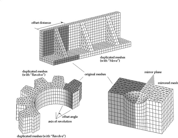
Duplicating volume meshes
|
|||
 |
|||
|
Examples
of duplicated volume meshes
|
|||
|
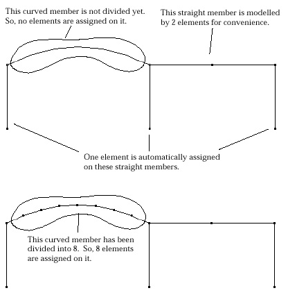
Creating frame elements using straight lines
or curves
|
|||
 |
|||
|
Example of element generation
on frame members
|
|||
|
Creating frame elements
using mesh generation functions
|
|||
 |
|||
|
Example of constructing
frame model using mesh generation
|
|||
|
|
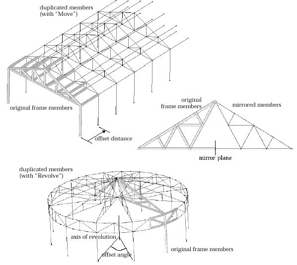
Duplicating frame elements
|
||
 |
|||
|
Examples of duplicated
frame members
|
|||
|
Modifying nodal coordinates
|
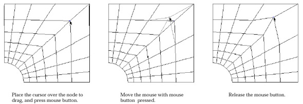
Dragging nodes using mouse
|
||
 |
|||
|
Process of dragging a
node
|
|||
|
Transforming meshes
|
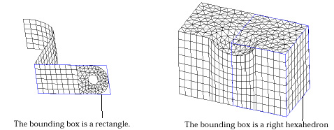
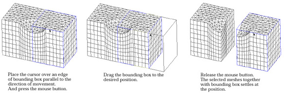
Moving meshes
|
||
 |
|||
 |
|||
|
Moving meshes by dragging the bounding box |
|||
|
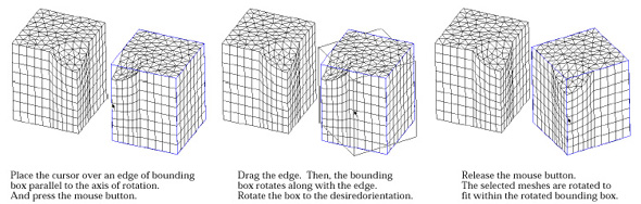
Rotating meshes
|
|||
 |
|||
|
Rotating meshes by dragging an edge of the bounding box |
|||
|
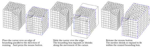
Resizing meshes
|
|||
 |
|||
|
Resizing meshes by rubber-banding an edge of the bounding box |
|||
|
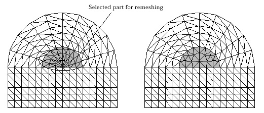
Remeshing
|
|||
 |
|||
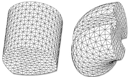
|
Example of remeshing |
|||
|
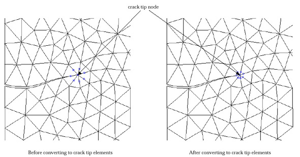
Making crack tip elements
|
|||
 |
|||
|
Example of creating crack tip elements |
|||
|
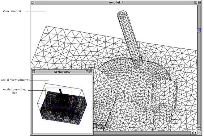
Aerial View
|
|||
 |
|||
|
The aerial view window
and the image display in the main window
|
|||
|
Data assignment
|
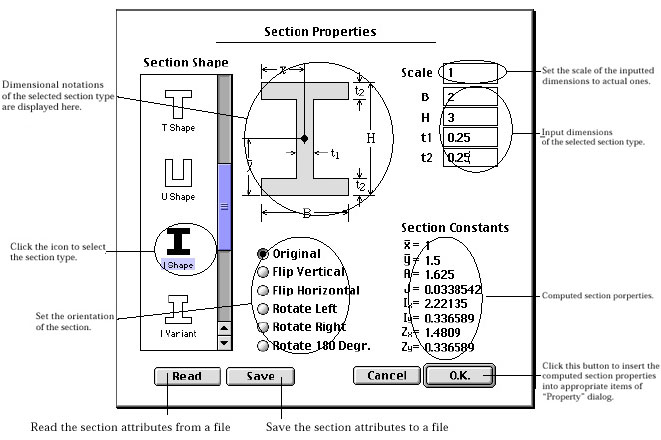
Defining cross sections
|
||
 |
|||
|
Section Properties
|
|||