![]()
![]()
![]()
![]()
| Curves and Surface Primitives > Creating Curves and Surface Primitives > Creating circles or circular arcs |
|
|
|
|
||
Creating circles or circular arcs
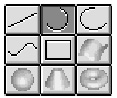 |
Press the circle tool button |
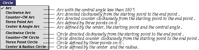
> Arc
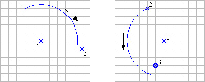
While this option is active, an arc is created by entering its center and two end points. The direction of the arc is determined so that its central angle become less than 180 . The following figure shows an example of creating a circular arc by application of this option. When the center and the starting point of the arc are entered, a full circle is drawn. This circle represents the possible path of the arc, which is finally set by entering the third point, i.e., the end point of the arc.
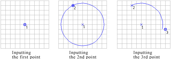
< Procedure of inputting a circular arc >
The end point may not coincide with the third input point as shown in this example. Then, the coordinates of the end point are determined so that the arc is trimmed by the line extending the center and the third input point.
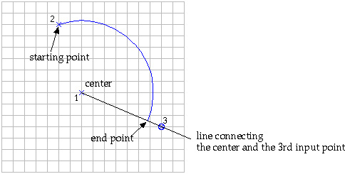
< Construction of an arc >
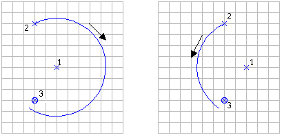
As shown below, the central angle of a arc made by this option is always less than 180 , and accordingly, the arc is directed from the starting point to the end point.
< The arcs are made so that their central angles are less than 180 >
> Clockwise Arc
While this option is active, a circular arc is created by entering its center and two end points. The arc is directed clockwise from the first end point to the second. The meaning of "clockwise" or "counter clockwise" is relative to the view direction in 3-dimensional space. That is, the direction is based on the current view of the screen. Therefore, a clockwise arc may look counter clockwise, when the screen view is reversed by rotating the view direction. However, the absolute direction of the arc in 3-dimensional space remains the same as created, regardless of the view transformation.
> Counter-CW Arc
While this option is active, a circular arc is created by entering its center and two end points. The arc is directed counter-clockwise from the first end point to the second. Here, the direction of the arc is based on the current view of the screen, as in the case of "Clockwise arc".
< Clockwise arc and counter-CW arc >
> Three Point Arc
While this option is active, a circular arc is created by entering three points on the arc consecutively, i.e. the starting point, a mid-point, and the terminal point. The arc is directed from the starting point through the mid-point to the terminal point.
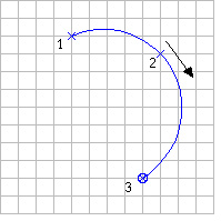
< Three point arc >
> Center & Angle Arc
A dialog box appears when this option is selected. A circular arc is created
by entering its center and the starting point, and specifying its central angle
using the text box of the dialog. The central angle is set initially as 90 in
the text box. ![]() The
central angle can be modified as desired by editing this text. i s dimmed at
the beginning, and is not in clickable state. Only after the center and the
starting point of an arc are entered, this button becomes enabled. A circle
is created by clicking this button, or pressing
The
central angle can be modified as desired by editing this text. i s dimmed at
the beginning, and is not in clickable state. Only after the center and the
starting point of an arc are entered, this button becomes enabled. A circle
is created by clicking this button, or pressing ![]() key
(Windows :
key
(Windows : ![]() key).
key).
> Clockwise Circle
While this option is active, a circle is created by entering its center and two other points. The first of the two points specifies the starting point of its circumference. The circle is directed clockwise from this point and back to the point. The second point is a point on the plane of the circle, but not on the line connecting the first and the second point. The plane of the circle is determined by entering this point.
The first two points are enough to define a circle on a plane, although one more point determining the plane of the circle is necessary in 3-dimensional modeling. However, VisualFEA asks for the 3rd point even in the case of planar modeling, because 3- dimensional data input is assumed regardless of the actual dimension of modeling.
> Counter-CW Circle
While this option is checked, a circle is created by entering three points in the same manner as in the case of "Clockwise Circle." The circle is directed counterclockwise
> Three Point Circle
While this option is checked, a circle is created by entering three points on the c i rcle consecutively, i.e. the starting point and two other points on the circumference. The circle is directed from the starting point toward the second.
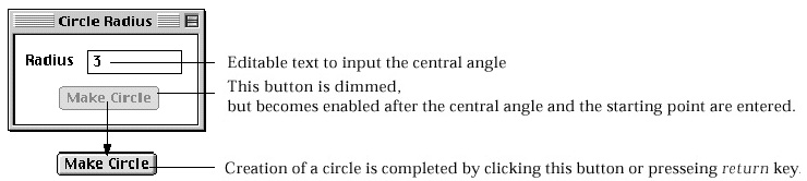
> Center & Radius Circle
A dialog box appears when this option is selected. A circle is created by entering
its center and specifying its radius using the text box of the dialog. At the
beginning, the radius is set as 1 in the text box. This radius can be modified
as desired by editing this text. ![]() is
dimmed at the beginning, and is not in clickable state. Only after the radius
and the center of a circle are entered, this button becomes enabled. A circle
is created by clicking this button, or pressing
is
dimmed at the beginning, and is not in clickable state. Only after the radius
and the center of a circle are entered, this button becomes enabled. A circle
is created by clicking this button, or pressing ![]() key
(Windows :
key
(Windows : ![]() key).
key).
|
|
|
|