Studying Stiffness Equation Assembly and Solution
|
Studying Stiffness Equation Assembly and Solution |
|
|
| |
||
Basic usage of the function
This function is only to simulate the assembly and solution process of the
stiffness equations. There fore, the actual data, analysis results and setting
of analysis options are not affected by this function. The usage of this function
is described below.
Starting the function
In order to initiate this function, first create the model whose global stiffness matrix is to be displayed, and assign the element properties and the boundary conditions.
Select "System Equations" item of "FEM Simulation" submenu
of ![]() menu
Then, "System Equations" window opens. The window opens only when
a model is created and assigned with element properties. The process of assembling
and solving the system equations is simulated and visualized on this window.
menu
Then, "System Equations" window opens. The window opens only when
a model is created and assigned with element properties. The process of assembling
and solving the system equations is simulated and visualized on this window.
Ending the function
The function is terminated by closing "Stiffness Matrix" window. Clicking
the close box of the window will close the window. This function may also be
terminated by starting any other menu function.
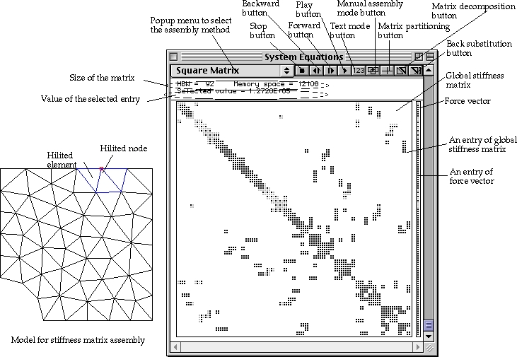
Contents of the "System Equations" window
The window contains the stiffness matrix, the force vector, a popup menu, control
buttons, and texts as shown in the figure below.
|
Stiffness matrix: The stiffness matrix is initially displayed in square matrix form, but can also be displayed in a few other forms. Each entry is represented by graphics or by text depending on setting of the display mode. |
|
| An entry is represented by one of the following 4 different appearances: | |
| - Empty Entry : These are the entries with no contribution from element stiffness matrices. They are not associated with any d.o.f. in the model. They have 0 values in actual stiffness matrix. Their space are left blank. | |
| - Zero Entry : These are the entries associated with one or more d.o.f. in the model, but their numerical value is zero. These entries are represented by hollow square boxes, , or numerical value 0. | |
| - Non-boundary entries : These entries are not associated with d.o.f. constrained by boundary conditions. They are represented by black square boxes, , or by black text like . | |
| - Boundary entries : These entries are associated with constrained d.o.f. They are represented by gray square boxes, , or by gray text like . | |
|
Force vector: The force vector is displayed to the right of the stiffness matrix. The appearance and the control of the force vector entries are the same as the stiffness matrix. |
|
| Popup menu: The popup menu has the items for selection of assembly methods. The stiffness matrix is displayed by the selected method. |
<Displaying the global Stiffness matrix>
|
Control buttons: There are 9 buttons to control the display of the stiffness matrix. |
|
| Texts: There are texts indicating the half band width of the matrix, the required computer memory to store the assembled matrix, and the numerical value of the selected entry. |
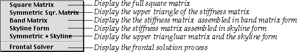
Selecting the assembly method
There are numerous methods of assembling and solving the system equations in finite element method. A number of typical methods are included in the function, and are shown as items in the popup menu at the top left corner of the window.
Texts related to the matrix as well as the image of the matrix is renewed immediately after the menu item is selected.
Using control buttons
There are 7 control buttons at the top of “Stiffness Assembly” window. They
are used in controlling the display of the global stiffness matrix or animation
of its assembly and elimination procedure.
Getting the information on an entry of the equations
An entry of the stiffness matrix and the force vector can be selected by clicking
the displayed text or image of the entry. The identity of a selected entry and
its related information can be obtained from the following responses.
| The selected entry is highlighted in red. | |
| If the assembly method is set as “Symmetric + Skyline”, the corresponding entries in both matrices are highlighted. | |
| The numerical value of the entry is displayed with label “Selected value”
in “System Equations” window. If the stiffness matrix assembly is not completed at the time of selection, a partially assembled value may be displayed. |
|
| Elements and nodes associated with the selected entry are highlighted in the main window. |
The selection can be switched from one entry to another without interruption by moving the cursor with the mouse button pressed.
Finding entries associated with an element
Simply click a desired element, in order to find which entries get contribution from the stiffness matrix of the element. The element is highlighted in red, and at the same time, all the entries associated with the element are also marked in red. If you select multiple elements using shift click or rubber band rectangle, the selected elements are highlighted in blue, and all the entries associated with the selected elements are highlighted in blue. In this case, the last selected element is highlighted in red, and its associated entries are also highlighted in red.
Displaying the system equations in text mode
There are 2 modes of displaying the system equations: graphic mode and text
mode. The numerical values of the stiffness matrix and the force vector are
represented by text strings in text mode. If ![]() button
is shown as pressed like
button
is shown as pressed like ![]() ,
the system equations are displayed in text mode , and in graphic mode otherwise.
Click
,
the system equations are displayed in text mode , and in graphic mode otherwise.
Click ![]() button
to toggle the display mode between graphic mode and text mode. In text mode,
only part of the equations are usually displayed, as the display takes larger
space. Scrolling and resizing the window are necessary to display the
button
to toggle the display mode between graphic mode and text mode. In text mode,
only part of the equations are usually displayed, as the display takes larger
space. Scrolling and resizing the window are necessary to display the
hidden part of the system equations.
Scrolling, resizing and zooming the window
The contents of “Stiffness Matrix” window can be scrolled using horizontal or
vertical scroll bars. Only the stiffness matrix part is scrolled. The window
may be resized or zoomed if necessary, by dragging the resize box or clicking
the zoom box of the window.
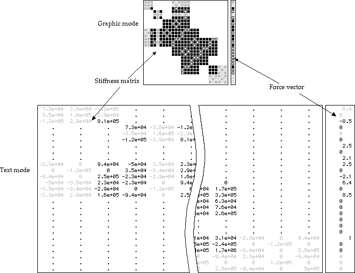
< Displaying the system equations in graphic mode and in text mode >
|
|
|
|